





How a 120,000 m³/d Municipal WWTP Cut Aeration Energy by 48% with Fine Bubble Disc Diffusers
Sector: Municipal Wastewater Treatment | Technology: Fine Bubble Disc Diffuser | Scale: 10,608 units across two biological treatment phases

Project Overview
A large-scale municipal wastewater treatment facility (WWTP) in East Asia with a total design capacity of 120,000 m³/d operates across four sequential construction phases. The facility serves a dense urban catchment and is subject to Class I-A effluent discharge standards for ammonia-nitrogen.
Two phases - Phase I (50,000 m³/d) and Phase IV (20,000 m³/d) - had been in continuous operation for many years without aeration system replacement. As the original diffusers deteriorated, the facility's operations team observed rising energy consumption, unstable dissolved-oxygen (DO) distribution, and increasing maintenance burden. Facing a clear performance and compliance gap, the plant management commissioned Aquasust to design and execute a full aeration system upgrade across both phases simultaneously.
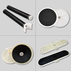
The project, delivered by Aquasust's engineering team in a phased retrofit over approximately two months, replaced a combined total of 10,608 diffuser units, converting both phases from aging legacy equipment to a uniform Aquasust Φ270 mm EPDM fine bubble disc diffuser platform.
The Challenge
2.1 Phase I: Tube Diffuser Clogging and Structural Decay
Phase I's biological reaction tanks were originally equipped with 2,248 tube diffuser units operating at a nominal airflow of 8 Nm³/h per unit. After years of service, the system exhibited characteristic signs of late-stage membrane fatigue:
Membrane pore blockage
- micro-pore fouling by biofilm and inorganic scaling caused bubble coalescence, shifting the system from fine-bubble to coarse-bubble mode and sharply reducing oxygen transfer efficiency (OTE).
Structural aging
- EPDM membrane cracking and fitting corrosion created air channeling, generating large-diameter bubble plumes with minimal surface-area contact.
Energy waste
- blowers operated at elevated discharge pressure (76 kPa against a design ceiling of 81 kPa), consuming nearly 0.146 kWh per cubic meter of treated wastewater - almost at capacity headroom.
Dead zones and sludge sedimentation
- with insufficient and unevenly distributed airflow, quiescent pockets formed beneath the tube arrays, causing sludge accumulation and creating localised anaerobic micro-environments.
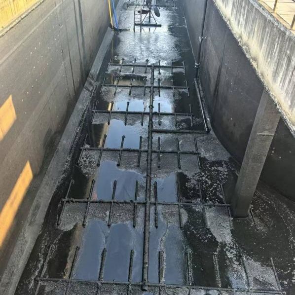
When individual diffuser airflow drops below the design threshold, the consequences propagate across the entire bioprocess:
|
Symptom |
Root Cause |
|
OTE decline |
Bubble diameter growth, reduced air-water contact area |
|
Rising blower pressure |
Increased membrane resistance from fouling |
|
Sludge dead zones |
Inadequate bottom-scouring velocity |
|
H₂S odour events |
Localised anaerobic zones releasing sulphide |
|
NH₃-N effluent spikes |
Suppressed nitrification under DO deficit |
|
Higher maintenance cost |
Escalating unit replacement and cleaning frequency |
2.2 Phase IV: Aged Disc Diffuser Failure
Phase IV was originally fitted with 3,722 disc diffusers of the same 270 mm format but an earlier product generation. After the manufacturer's rated service life had been substantially exceeded, membrane integrity collapsed. Stress cracks propagated across multiple units simultaneously, rendering the diffuser mat functionally equivalent to an open-pipe system. Blower discharge pressure had stabilised at 57.3 kPa (design ceiling: 61 kPa) - operating with minimal safety margin and producing coarse-bubble aeration at increasing energy cost.
Engineering Approach
3.1 Diffuser Selection Logic
Aquasust recommended a uniform upgrade to the Φ270 mm EPDM fine bubble disc diffuser across both phases based on three engineering criteria:
Proven oxygen transfer efficiency:
At the design airflow range of 2.0–6.0 Nm³/h per unit, the Φ270 format achieves a standard oxygen transfer efficiency (SOTE) of ≥30% in clean water, corresponding to a theoretical aeration efficiency of ≥4.5 kgO₂/kWh.
Optimal service area coverage:
The 0.4–0.8 m²/unit service area specification aligns with the tank floor geometry for both Phase I and Phase IV, enabling dense but non-overlapping coverage.
Reduced system pressure:
At equivalent treatment capacity, the Φ270 disc format operates at a substantially lower air resistance loss (≤3.5 kPa) than the legacy tube diffuser array, directly reducing blower operating pressure and extending blower mechanical life.
3.2 Hydraulic and Aeration Design Verification
Phase I
Effective aeration floor area: ~3,800 m²
Total diffusers installed: 7,532 units
Resulting service area: 0.50 m²/unit (within 0.4–0.8 m² design optimum)
Blower configuration: two active + one standby, rated airflow 150 m³/min
Unit airflow at design condition: 2.39 Nm³/h/unit (within 2.0–6.0 Nm³/h operating window)
Phase IV
Effective aeration floor area: ~1,665 m²
Total diffusers installed: 3,076 units
Resulting service area: 0.547 m²/unit (within design optimum)
Blower configuration: two active + one standby, rated airflow 60 m³/min
Unit airflow at design condition: 2.34 Nm³/h/unit (within operating window)
Both phases operate in the lower-mid band of the 2.0–6.0 Nm³/h range, ensuring micro-bubble generation, complete floor coverage, and a comfortable margin below the upper airflow threshold that causes membrane distortion.
Solution & Scope of Supply
Aquasust supplied and installed a comprehensive aeration upgrade package across both treatment phases. The scope covered not only the diffuser elements but also the full ancillary infrastructure required for long-term, low-maintenance operation.

4.1 Φ270 mm EPDM Fine Bubble Disc Diffuser - Technical Specification
|
Parameter |
Specification |
|
Model |
Φ270 mm EPDM Disc Diffuser |
|
Air flow range |
2.0 – 6.0 Nm³/h per unit |
|
Bubble diameter |
≤ 2 mm |
|
SOTE (clean water) |
≥ 30% |
|
Oxygen transfer capacity |
≥ 0.13 kgO₂/h per unit |
|
Theoretical aeration efficiency |
≥ 4.5 kgO₂/kWh |
|
Air pressure loss |
≤ 3.5 kPa |
|
Service life |
≥ 5 years |
|
Optimal service area |
0.4 – 0.8 m²/unit |
4.2 Diffuser Quantity Summary
|
Treatment Phase |
Design Capacity |
Units Replaced (Legacy) |
Aquasust Φ270 Units Installed |
|
Phase I |
50,000 m³/d |
2,248 tube diffusers |
7,532 |
|
Phase IV |
20,000 m³/d |
3,722 disc diffusers (aged) |
3,076 |
|
Total |
70,000 m³/d |
5,970 |
10,608 |
4.3 Ancillary Equipment
Air purge silencers (gas relief/blowdown) for blower protection during maintenance
UPVC drain valves at tank low points to facilitate future dewatering and diffuser inspection
Twelve (12) 304 stainless-steel membrane acid-wash assemblies (Phase IV) for in-situ EPDM membrane cleaning without full tank dewatering
Installation & Commissioning
Aquasust executed the retrofit in two sequential site phases, prioritising minimal disruption to plant-wide treatment capacity. The standard four-step process was applied to each phase:
Tank Dewatering & Inspection
Each biological reaction tank was taken offline in rotation, sludge was transferred to adjacent active tanks, and the tank was drained. Aquasust site engineers conducted a full condition survey of the existing lateral piping, main aeration headers, and anchor points before any demolition began.
Legacy System Removal
All existing diffuser units, saddles, and connecting fittings were systematically removed. Where tube diffuser laterals were beyond serviceable condition, the pipe network was also replaced. Debris was cleared, and the tank floor was prepared to the specified installation datum for the new disc diffuser grid.
Aquasust Φ270 Disc Diffuser Installation
The new EPDM disc diffusers were installed in the engineered grid pattern per the hydraulic design, with each unit torque-set to prevent air bypass at the connection saddle. Lateral piping, main headers, drain valves, and purge assemblies were then commissioned and pressure-tested before tank refilling.
Gradual Commissioning & DO Verification
Tanks were refilled, blowers started at reduced load, and DO readings were taken at multiple points across the tank grid during the initial 24-hour ramp-up period. Airflow was progressively increased to operating set-point. Process data confirmed uniform DO distribution and stable nitrification within the normal warm-up window.

Total on-site duration: Phase IV - 16 days; Phase I - 41 days (reflecting larger tank count and diffuser volume).

Verified Results
Performance data was recorded and compared on a like-for-like basis (same calendar quarter, year-over-year), eliminating seasonal temperature and influent loading variability from the analysis.
6.1 Consolidated Performance Comparison
|
KPI |
Phase I - Before |
Phase I - After |
Change |
|
Daily treated volume (m³/d) |
43,800 |
51,400 |
+17.5% |
|
Active blowers running |
2 |
1 |
–50% |
|
Blower discharge pressure (kPa) |
76 |
62 |
–18.4% |
|
Unit energy consumption (kWh/m³) |
0.146 |
0.075 |
–48.6% |
|
Effluent NH₃-N (mg/L) |
0.456 |
0.231 |
Compliant |
|
Monthly NH₃-N removal (tonnes/month) |
30.5 |
64.8 |
+112% |
|
KPI |
Phase IV - Before |
Phase IV - After |
Change |
|
Daily treated volume (m³/d) |
20,600 |
23,300 |
+12.9% |
|
Blower discharge pressure (kPa) |
57.3 |
51.6 |
–9.95% |
|
Unit energy consumption (kWh/m³) |
0.155 |
0.089 |
–42.6% |
|
Effluent NH₃-N (mg/L) |
0.316 |
0.238 |
Compliant |
|
Monthly NH₃-N removal (tonnes/month) |
14.4 |
29.3 |
+103% |
6.2 Energy Reduction - The Primary Driver
The most significant operational benefit is the reduction in unit aeration energy: Phase I dropped from 0.146 to 0.075 kWh/m³ (–48.6%), and Phase IV from 0.155 to 0.089 kWh/m³ (–42.6%). At both phases combined, the facility now treats a higher daily volume while running fewer blowers at lower pressure.
The Phase I shift from two active blowers to one - at nearly double the throughput - is the clearest demonstration of the efficiency gain. Estimated simple payback on the capital investment is within approximately 18 months based on operational electricity savings alone.
6.3 Blower Pressure Reduction - Engineering Safety Margin
The decrease in blower discharge pressure is not merely an energy saving; it carries structural and reliability value:
Phase I: Pressure dropped from 76 kPa to 62 kPa against a design ceiling of 81 kPa. The operating-to-ceiling gap widened from 5 kPa to 19 kPa - nearly quadrupling the safe operating headroom.
Phase IV: Pressure dropped from 57.3 kPa to 51.6 kPa against a ceiling of 61 kPa. The headroom more than doubled.
Lower operating pressure means reduced thermal and mechanical stress on blower bearings, impellers, and motors, extending equipment service life and lowering the probability of safety valve actuation, pipe joint leakage, and unplanned shutdowns.
6.4 Ammonia-Nitrogen Removal - Compliance and Treatment Intensification
Despite treating a greater daily volume, both phases maintained effluent NH₃-N well below Class I-A thresholds. More significantly, the total mass of ammonia removed per month more than doubled:
Phase I: from 30.5 to 64.8 tonnes/month (+112%)
Phase IV: from 14.4 to 29.3 tonnes/month (+103%)
This result reflects the improved DO distribution enabling full and stable nitrification across the entire tank volume - a direct consequence of the uniform fine-bubble coverage delivered by the Aquasust Φ270 disc diffuser grid.
Why Aquasust
Aquasust specialises in the engineering, manufacture, and site implementation of fine bubble aeration systems for municipal and industrial wastewater treatment. This project demonstrates the full-stack capability that distinguishes Aquasust from a diffuser-only supplier:

Design-build delivery
From hydraulic modelling and diffuser layout optimisation to on-site installation management and process commissioning
Performance-backed specification
Every Aquasust Φ270 EPDM disc diffuser is manufactured to ≥30% SOTE and ≥4.5 kgO₂/kWh efficiency, independently verifiable against GB/T 17393 test protocols
Ancillary integration
Air purge assemblies, drain valves, and acid-wash systems are supplied as a coordinated package, not afterthoughts
Proven field results
Documented post-retrofit energy reduction of 42–49%, ammonia removal improvement of >100%, and blower pressure reduction of up to 18% in a real municipal operating environment
Ready to evaluate an aeration upgrade for your facility?
Contact the Aquasust engineering team with your tank dimensions, design flow, and existing blower specification. We will prepare a preliminary diffuser layout, service-area calculation, and projected energy saving estimate at no cost.
Explore the Aquasust Φ270 mm EPDM Disc Diffuser
Aeration System Retrofit Services
Request a Project Assessment