





Plan Drawings

List of Materials
|
No. |
Material Name |
Specification |
Unit |
Quantity |
Material |
Remarks |
|
1 |
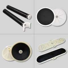
Disc Diffuser |
φ300 |
pcs |
2126 |
EPDM |
|
|
2 |
Clamp Connector |
DN50-20 |
pcs |
2126 |
ABS |
|
|
3 |
Main Pipe |
DN80 |
meters |
573.1 |
UPVC |
6m(Vertical Pipe)*28 pcs 5.4m * 28 pcs 4.8m * 28 pcs 4.7m * 15 pcs 4. 1m * 4 pcs 3.5m * 8 pcs 2.9m * 1 pcs 1.7m * 1 pcs |
|
4 |
Main Pipe |
DN65 |
meters |
233.6 |
UPVC |
6m(Vertical Pipe) * 16 pcs 4.8m * 16 pcs 4.1m * 12 pcs 2.9m * 4 pcs |
|
5 |
Branch Pipe |
DN50 |
meters |
1275.6 |
UPVC |
5.4m * 102 pcs 4.8m * 151 pcs |
|
6 |
Equal Tee |
DN80 |
pcs |
28 |
UPVC |
|
|
7 |
Equal Tee |
DN65 |
pcs |
16 |
UPVC |
|
|
8 |
Flange |
DN80 |
pcs |
28 |
UPVC |
|
|
9 |
Flange |
DN65 |
pcs |
16 |
UPVC |
|
|
10 |
Reducer Tee |
DN80-50 |
pcs |
204 |
UPVC |
|
|
11 |
Reducer Tee |
DN65-50 |
pcs |
104 |
UPVC |
|
|
12 |
Elbow |
DN80 |
pcs |
114 |
UPVC |
|
|
13 |
Elbow |
DN65 |
pcs |
64 |
UPVC |
|
|
14 |
Straight Connector |
DN50 |
pcs |
102 |
UPVC |
|
|
15 |
Air-Water Drainage |
DN20 |
set |
22 |
UPVC |
|
|
16 |
Pipe |
DN20 |
meters |
176 |
UPVC |
For air-water drainage system |
|
17 |
Elbow |
DN20 |
pcs |
110 |
UPVC |
|
|
18 |
Ball Valve |
DN20 |
pcs |
22 |
UPVC |
|
|
19 |
Single Thread Adapter |
DN20 |
pcs |
22 |
UPVC |
|
|
20 |
Saddle Clip |
DN20 |
set |
110 |
304 |
|
|
21 |
Expansion Bolt |
M6*70 |
set |
220 |
304 |
|
|
22 |
Clamp Connector |
DN80-20 |
pcs |
14 |
ABS |
|
|
23 |
Clamp Connector |
DN65-20 |
pcs |
8 |
ABS |
|
|
24 |
Single Hole Bracket |
DN50 |
pcs |
360 |
ABS |
|
|
25 |
Adjustable Bracket |
DN80 |
set |
240 |
304 |
|
|
26 |
Adjustable Bracket |
DN65 |
set |
108 |
304 |
|
|
27 |
Adjustable Bracket |
DN50 |
set |
401 |
304 |
|
|
28 |
Vertical Pipe Bracket |
DN80 |
set |
56 |
304 |
|
|
29 |
Vertical Pipe Bracket |
DN65 |
set |
32 |
304 |
|
|
30 |
Expansion Bolt |
M8*80 |
set |
360 |
304 |
|
|
31 |
Flange Bolt |
M16*80 |
set |
352 |
304 |
|
|
32 |
Gasket |
DN80 |
pcs |
28 |
Rubber |
|
|
33 |
Gasket |
DN65 |
pcs |
16 |
Rubber |
|
|
34 |
Glue |
bottle |
22 |
Installation Notice for Disc Diffuser
3.1 Overview
The aeration is one of the common crafts in Wastewater treatment solutions. The aeration system includes large quantity of aeration diffusers. These diffusers are made of parts such as rubber and plastic, and are extremely prone to damage. Therefore, the installation of the aeration system requires suitable conditions, or the subsequent operating may be affected.
In a sewage treatment plant, the aeration system is often the last part to be installed. Once it is installed in place, the sewage treatment plant can start running.
3.2 Installation Conditions
The following conditions are required during the installation of the aeration system:
(1) In terms of the aeration tank part:
- The construction of the aerobic tank project should be completed.
- The concrete should be fully dry so that it is sufficient to fix the expansion bolts.
- The bottom of the aeration tank should be cleaned thoroughly, with no accumulated water or sundries.
(2) The railings and walkways on the tank surface should be installed, and safety measures should be in place.
(3) The blowers and air ducts should be installed (all steel pipes must be completely installed, and they shall not be installed simultaneously with the bottom aeration system. Otherwise, there will be potential safety hazards in the installation, such as insufficient safety protection and welding sparks that may damage the bottom plastic pipes, etc.). It should be ready for air supply.
(4) The water supply conditions must be fully met, and the water supply facilities should be arranged in advance.
Fill water into the aerobic tank for commissioning, check whether the pipes are leaking, and ensure the water level of the diffusers and the aeration balance.
The aeration system should be immersed in water immediately after installation.
Since rubber and plastic components are high-molecular materials, they are prone to aging and damage when exposed to sunlight. If the water supply conditions are not met, the installation should be postponed until the water supply conditions are satisfied.
Only when all these installation conditions are fully met can the aeration system be installed. Otherwise, it may affect the subsequent aeration effect. Any quality issues with the aeration system caused by unmet installation conditions are not the responsibility of the supplier or installer.
3.3 Installation Procedure
(1) Review the installation construction drawings and verify if the site meets the installation conditions.
(2) Check if the dimensions of the site pool match the construction drawings.
(3) Mark lines according to the site conditions and the drawings.
(4) Drill expansion bolts along the lines and install adjustable pipe brackets.
(5) Cut pipes according to the dimensions specified in the drawings.
(6) Position the main air intake pipe and glue the matching four-way or reducing tee fittings (Note: ensure horizontal and vertical alignment).
(7) Mark lines and drill holes on the branch pipes according to the diffuser positions in the drawings. The hole size is generally 6-8mm, depending on the specific diffuser model (Ensure to clean the debris after drilling; no debris should remain in the piping).
(8) Place the branch pipes on the adjustable pipe brackets and glue them to the central air intake pipe (Note: ensure the drilled holes on the branch pipes face vertically upwards).
(9) Glue the tee and elbow connectors of the side pipes to the branch pipe openings (Note: ensure horizontal and vertical alignment).
(10) Adjust the overall level of the piping using the adjustable pipe brackets.
(11) Fasten the adjustable pipe brackets with nylon ties (Method: Clip the hole-less side of the nylon tie into the slot of the bracket, then insert a 12mm iron rod into the square hole of the tie and press down gently to secure it).
(12) Glue the diffuser connectors to the drilled positions on the branch pipes (Note: ensure the diffuser connectors face vertically upwards).
(13) Install the diffusers.
(14) After the diffusers and piping are installed, fill the tank with water up to about 100mm above the diffusers to test for air leaks in the pipe connections. If any leaks are found, mark and repair them promptly. Once everything is tested and qualified, the system can be officially put into operation.
3.4 Usage and Warranty
(1) This product is only suitable for the following conditions:
(a.) Water Temperature: 10-50 ℃
(b.) Water Quality: The incoming water quality must meet the water quality specified in the contract drawings.
(c.) Air Volume: Must meet design requirements.
(2) After installation and commissioning, if water operations cannot start immediately, the aeration tank should be filled with at least 1.5 meters of water for protection. Having water in the tank can prevent damage to the aeration system from sunlight, freezing, and other extreme weather conditions, as well as protect against falling objects damaging the system.
Note: Due to regional climate differences, water levels in the aeration tank should not be less than 1 meter from June to September and not less than 1.5 meters from January to May and October to December.
(3) Disc diffuser replacement due to the following conditions and circumstances are not covered by the warranty:
(a.) Damage to the aeration system caused by subsequent construction, such as falling objects damaging the equipment or welding slag burning the system, after the aeration system installation.
(b.) Failure to fill the tank with water promptly after installation, causing system aging due to sunlight exposure or system cracking due to low temperatures.
(c.) Operation in wastewater with unstable water quality, such as strong acids, strong alkalis, viscosity, or a large amount of oil, causing membrane softening or membrane pore clogging.
(d.) Poor air quality in the aeration air, with oil contamination from the blower entering the pipes, causing damage to the aeration system membranes.
(e.) Failure to follow operational procedures during operation, insufficient or excessive airflow causing damage to the aeration system; sludge settling on the membrane after stopping the air, forcibly aerating, causing membrane overloading and rupture.
(f.) Damage caused by improper use, maintenance, or storage, or damage caused by force majeure or self-disassembly.
(g.) If commissioning cannot be conducted within one week after installation, the system is not covered by warranty.
3.5 Precautions:
(a.) To prevent damage to the aeration devices from other operations, such as welding sparks and civil construction, the aeration piping system must be installed only after all surrounding facilities of the aeration tank have been completed.
(b.) If the client specifically requests delivery and installation first, without direct commissioning, any additional costs for secondary installation and commissioning, such as labor, transportation, accommodation, and meal allowances, will be borne by the client.
(c.) Upon delivery to the client's site, the client is responsible for signing off on receipt and has an obligation to safeguard the goods.
Installation Process Photos and Videos
4.1 Arrival at the Project Site

4.2 Project Site Overview


4.3 Installation Progress
4.3.1 Placement of Aeration Pipes According to Construction Drawings


4.3.2 Install Clamp Connectors and Perform Leveling Adjustment


4.3.3 Secure Aeration Pipes with Expansion Bolts


4.3.4 Install Diffusers


4.3.5 Water Inlet Commissioning


4.3.6 Acceptance Passed, Put into Operation

